This software supports programming of Atmel microcontrollers 89Sxx ('51), ATtiny, ATmega and 90Sxx (AVR). It can erase built-in Flash and EEPROM memories as well as read and program them. ISP Programmer also supports serial Atmel DataFlash memories. Communication with devices is made serially in system (ISP - In-System Programming) without the need to pull the chip out of the socket or desolder it.
The microcontroller you want to program needs to be connected to the printer port (LPT) of the computer (directly with wires, without STROBE signal), according to this list: Microcontroller LPT port LPT port
signal signal pin number
[STROBE] ---- STROBE 1
RESET ---- AUTOLF 14
MOSI ---- INIT 16
SCK ---- SLCT-IN 17
MISO ---- ACK 10
GND ---- GND 25
[STROBE] ---- STROBE 1
RESET ---- AUTOLF 14
MOSI ---- INIT 16
SCK ---- SLCT-IN 17
MISO ---- ACK 10
GND ---- GND 25
STROBE signal connected to pin 1 of LPT port is used to control enabling of 3-state buffers of programming serial bus (SCK,MISO,MOSI). Using it is optional. But in case of connecting LPT port directly to microcontroller pins, you should use the same logic levels (ground / 5V) as LPT port in host and verify that programming would not brake the normal operation of the peripherials connected to this microcontroller. For example programming signals should not be connected to the enable pin of the LCD.
Below you can see the example schematic of the programming cable using 3-state buffer:
Below you can see the example schematic of the programming cable using 3-state buffer:

Connection of the programming cable to the microcontroller pins depends on the type of MCU, see the documentation at the Atmel's website.
With the ISP Programmer you are able to use any programming cable pinout, including AT-Prog, SI-Prog, UISP, STK200/300 and AEC ISP. You can choose any pins of the LPT port for programming signals, as well as define arbitrary RESET signal level.
WARNING: In case of programming Atmel DataFlash memories, RESET signal defined in pinout must be connected with ChipSelect (/CS) line of the chip.
Supported microcontrollers:
- AT89S2051, AT89S4051, AT89S51, AT89LS51, AT89S52, AT89LS52, AT89S53, AT89S8252, AT89S8253
- AT90S1200, AT90S2313, AT90S2323, AT90S2333, AT90S2343, AT90S4414, AT90S4433, AT90S4434, AT90S8515, AT90S8535, AT90CAN32, AT90CAN64, AT90CAN128, AT90PWM2, AT90PWM3, AT90USB646, AT90USB647, AT90USB82, AT90USB162, AT90USB1286, AT90USB1287
- ATtiny12, ATtiny13, ATtiny15, ATtiny24, ATtiny25, ATtiny26, ATtiny44, ATtiny45, ATtiny84, ATtiny85, ATtiny261, ATtiny461, ATtiny861, ATtiny2313
- ATmega48, ATmega48P, ATmega8, ATmega88, ATmega88P, ATmega8515, ATmega8535, ATmega16, ATmega161, ATmega162, ATmega163, ATmega164P, ATmega165P, ATmega168, ATmega168P, ATmega169, ATmega32, ATmega323, ATmega324P, ATmega325, ATmega328P, ATmega329, ATmega64, ATmega128, ATmega640, ATmega644, ATmega644P, ATmega645, ATmega649, ATmega1280, ATmega1281, ATmega2560, ATmega2561, ATmega3250, ATmega3290, ATmega6450, ATmega6490
- AT45DB011B, AT45DB011D, AT45DB021B, AT45DB021D, AT45DB041B, AT45DB041D, AT45DB081B, AT45DB081D, AT45DB161B, AT45DB161D, AT45DB321B, AT45DB321C, AT45DB321D, AT45DB642D, AT45CS1282
- AT25DF021, AT25DF041A, AT25DF081, AT26DF081, AT25DF161, AT26DF161, AT25DF321, AT25DF641, AT25F512B, AT25FS010, AT26F004
This software runs in Windows 95, 98, Me, NT 4.0, 2000, XP, 2003, Vista and Windows 7 (32-bit and 64-bit versions).
The screenshots of ISP Programmer running in Windows 7 64-bit:

PonyProg is a free serial device programmer software with a user friendly GUI framework available for Windows and Linux. You can download PonyProg here and install. Its purpose is reading and writing every serial device using either the serial or parallel port on a PC. At the moment following devices are currently supported with PonyProg software.
AVR Microcontroller AT90S1200 AT90S2313 AT90S2323 AT90S2333 AT90S2343 AT90S4414 AT90S4433 AT90S4434 AT90S8515 AT90S8534 AT90S8535 AT90can32 AT90can64 AT90can128 (untested) ATtiny12 ATtiny13 ATtiny15 ATtiny25 ATtiny26 ATtiny45 ATtiny85 ATtiny261 ATtiny461 ATtiny861 ATtiny2313 ATmega103 ATmega128 ATmega1280 ATmega1281 ATmega16 ATmega161 ATmega162 ATmega163 ATmega164 ATmega168 ATmega169 ATmega2560 ATmega2561 ATmega32 ATmega323 ATmega324 ATmega44 ATmega64 ATmega640 ATmega644 ATmega88 AT89S8252 AT89S53
PIC Microcontroller 12C508 12C509 12C671 12C672 16F627 16F628 16C84 16F84 16F84A 16F873 16F873A 16F874 16F874A 16F876 16F876A 16F877 16F877A
I²C Bus EEPROM 24C01 24C02 24C04 24C08 24C16 24C32 24C64 24C65 24C128 24C256 24C512 24C325 24C645 AT17C65 AT17C128 AT17C256 AT17C512 AT17C010
SPI EEPROM 25010 25020 25040 25080 25160 25320 25640 25128 25256 25642 95640 NVM3060 MDA2061 MDA2062 X2444 X2445
Siemens EEPROM SDE2506 SDE2516 SDE2526 SDA2546 SDA2586 SDA3546 SDA3586
Microwire EEPROM 93C06 93C46 93C56 93C57 93C66 93C76 93C86 93C13 (as a 93C06) 93C14 (as a 93C46)
Setting up the PonyProg environment
When we first start PonyProg this is the screen we see, click OK to start.


Setting up the Hardware
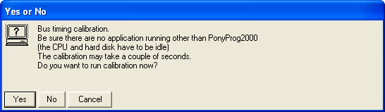
Goto Setup->Interface Setup to setup the hardware.
Goto Setup->Interface Setup to setup the hardware.

Set all the parameter as follows and click OK


我做的AVR 系列cpu 下載線 (ISP download cabel)

ISP下載線電路 (ISP download cabel circuit)
我做的AVR 開發系統板+TFT LCD pannel(2.4inch,320X240 解析度, 18bits color)+power supple(1.8v+2.5v+3.3V+5V)+xilinux FPGA+xilinux CPLD+altera FPGA+altera CPLD+USB+keyboard+Dsub interface(VGA)

ponyProg source code
ponyProg各種版本LINK:
截至目前(2012/03/21),已出至2.08b 版,但此版尚未測過,不知是否有bug.
目前用v2.07c BETA版
Programming an AVR Microcontroller using ponyProg(v2.07c BETA)
ponyProg2000簡介
PonyProg2000 is the programmer which is recommended for use with the AVR-PG1B programmer (made by Olimex and sold by SparkFun). I used v2.05a to make the following screenshot. Select the ATMega128 from the Device->AVR micro menu. Then bring up the Command->Security and Configuration Bits... dialog. The fuse settings should be modified to look like:

Make sure you click Write to program the ATMega128.
Each row corresponds to a fuse byte. If you consider checked = 0, unchecked = 1 and look at the bottom 3 rows, you'll get the following pattern (treat the grayed out SPIEN as being checked):
IMPORTANT: Make sure that the version of PonyProg2000 is at least version v2.06fBETA. Otherwise, there are some .hex files which PonyProg doesn't read properly.
ATMega169, ATMega169L, ATMega169V, Security bits

PonyProg2000 is the programmer which is recommended for use with the AVR-PG1B programmer (made by Olimex and sold by SparkFun). I used v2.05a to make the following screenshot. Select the ATMega128 from the Device->AVR micro menu. Then bring up the Command->Security and Configuration Bits... dialog. The fuse settings should be modified to look like:

Make sure you click Write to program the ATMega128.
Each row corresponds to a fuse byte. If you consider checked = 0, unchecked = 1 and look at the bottom 3 rows, you'll get the following pattern (treat the grayed out SPIEN as being checked):
11111111 = 0xFF
11001001 = 0xC9
10111111 = 0xBF
You'll notice that this corresponds to the fuse settings shown in the examples above.
IMPORTANT: Make sure that the version of PonyProg2000 is at least version v2.06fBETA. Otherwise, there are some .hex files which PonyProg doesn't read properly.
ATMega169, ATMega169L, ATMega169V, Security bits
沒有留言:
張貼留言
注意:只有此網誌的成員可以留言。