http://www.ti.com.tw/articles/default.asp
TI首頁 > 技術專欄
> DSP
> 放大器
> 介面產品
> 資料轉換器
> 電源管理
> 類比產品
> 無線通訊
> 寬頻
> DLP™
> LED
> 汽車電子
• 列出所有文章
三端並聯穩壓器的潛在應用
前言
許多半導體公司都提供三端並聯穩壓器 (three-terminal shunt regulator),這些元件內建精準參考電壓、運算放大器和用來控制精準電壓源的並聯電晶體 (shunt regulator),圖1就是典型的電路應用。三端並聯穩壓器是低成本的半導體元件,除了做為並聯穩壓器之外,它們對於其它電源供應設計也極有助益。這些半導體元件可擔任控制迴路裡的低成本運算放大器、搭配其它電晶體和被動零件或用於靴帶式電路 (boot-strap circuit);這些元件還能做為低功率輔助電源,專門供電給在低負載下操作的脈衝寬度調變 (PWM) 控制器。儘管這些電路不會出現在並聯穩壓器的元件資料表,但它們都是非常有用的應用。

圖1:並聯穩壓器 (Shunt Regulator)
運算放大器
在包含PWM而沒有電壓放大器的電源供應設計中,系統設計人員可利用並聯穩壓器做為低成本的運算放大器,圖2就是這類應用的功能方塊圖。方程式1代表其中補償電路的小訊號轉移函數。
 -- (1)
註:方程式1假設Rbias << Rz

圖2:PWM回授電路的運算放大器
這個電路還能增加光耦合器以提供某種電氣隔離,圖3就是隔離式回授電路線路圖。電阻R1提供偏壓給光耦合器和TL431,電阻R3和二極體D1提供固定偏壓點,確保偏壓電阻R1不會形成回授路徑。電阻R1和R2用來控制光耦合器增益;在絕大多數設計中,R1和R2的比值大約設為10比1。光耦合器有一個高頻極點 (fp),雖然元件資料表通常不會提供fp的資訊,但透過網路分析儀即可發現這個極點在許多應用中約為10 kHz。
 -- (2)

圖3:包含隔離電路的運算放大器回授電路
自舉電路 (Boot-Strap Circuit)
在交換式電源供應設計中,脈衝寬度調變器元件通常是由輔助線圈提供電源,其線路可參考圖4;這個電路的啟動需要小電流充電電阻 (Rt) 和電位保持電容 (Ch)。為了將功耗降至最低,小電流充電電阻值應越大越好。電位保持電容值也是越大越好,因為在電源供應開始工作之前,都須由它提供電源給PWM電路。

圖4:交換式電源供應的靴帶式電路
並聯穩壓器還能搭配雙極電晶體和數顆電阻以加快靴帶時間 (boot-strap time),詳細電路請參閱圖5。電路零件C、D1、Q1和Ra到Rd形成自舉電路。電源啟動後,電容C會完全放電,PWM的輸入電源值 (Vaux) 將由Q1和D1控制的串聯穩壓器決定。Vaux電壓在剛啟動時會在最高點 (Vaux_peak),其值由電阻Ra和Rb的比值決定。電容C和電阻Rc則用來決定自舉電路的關閉電壓和時間以節省電力。電阻Rd提供偏壓電流給TL431,電阻Re則會限制電流值,讓電晶體Q1保持在安全操作區 (Safe Operating Area)。

圖5:改良後的靴帶式電路
電路設計並不困難,只要選擇Ra和Rb來設定峰值充電電壓 (Vaux_peak)。
 -- (3)
選擇Rc電阻讓並聯電壓 (shunt voltage) 小於輔助線圈所提供的額定Vaux電壓 (Vaux_nominal)。
 -- (4)
電容C用來設定靴帶時間 (Tboot)。
 -- (5)
低功耗PWM偏壓供應
在某些電源供應裡,PWM電源是由類似圖4的輔助線圈提供,這個電路的問題在於負載很小時,輔助線圈將無法為元件提供足夠電源;此時PWM會啟動和關閉,使得電源供應可能出現異常行為。圖6電路顯示如何利用串聯穩壓器解決這個問題,這個穩壓器會在負載很小時啟動,等到偏壓線圈能夠提供電力給PWM控制器時就關閉。
電阻Ra到Rd、二極體D1和D2以及電晶體Q1組成低功率的偏壓供應電路,用來提供高於PWM關閉電壓和低於額定輔助線圈電壓 (Vaux_nominal) 的穩壓輸出,讓電晶體Q1如二極體OR電路作用:當PWM電源來自輔助線圈時,Vaux電壓成為逆向偏壓,使得電晶體Q1停止導通以節省電力;當電力洩漏使得Vaux電壓下降時,Q1會進入順向偏壓狀態,開始提供所需的電力給PWM控制器。
低功率串聯穩壓器的設計並不困難,只要為Rc選擇正確的電阻值,使其將適當的偏壓電流提供給D1,選擇Rd電阻值讓Q1在安全操作區工作,Ra和Rb的電阻值則用來設定低功率串聯穩壓器的輸出電壓,其值必須大於控制元件的啟動電壓,同時小於輔助線圈的額定供應電壓 (Vaux_nominal)。
我們可用下列方程式調整Ra和Rb組成的電阻分壓器。Q1射極電壓必須小於T1變壓器次級線圈提供的額定輔助電壓 (Vaux_nominal)。Vref是並聯穩壓器D1的內部參考電壓,Vd2和Vbeq1分別是二極體d2的電壓降和Q1的基極至射極電壓。
 -- (6)

圖6:低功率輔助電源供應
結論
TL431等三端並聯穩壓器對許多應用都極有幫助,它們不但成本低,用途又廣泛,可經由電路設計在交換式電源供應中執行許多功能。這些元件可做為高精準度的電壓參考,或是做為低成本的運算放大器以提供回授控制,它們還能做為比傳統方法更快的電源供應自舉電路。並聯穩壓器搭配一顆NPN電晶體即可組成低功率的偏壓供應,它會在負載很小的時候啟動,等到輔助線圈足以提供充份電力給PWM時再關閉。


other link :
實用低功耗設計原理、器件與應用
http://www.libone.com/ebook/T/A2025956.pdf
> 介面產品
> 資料轉換器
> 電源管理
> 類比產品
> 無線通訊
> 寬頻
> DLP™
> LED
> 汽車電子
• 列出所有文章
三端並聯穩壓器的潛在應用
前言
許多半導體公司都提供三端並聯穩壓器 (three-terminal shunt regulator),這些元件內建精準參考電壓、運算放大器和用來控制精準電壓源的並聯電晶體 (shunt regulator),圖1就是典型的電路應用。三端並聯穩壓器是低成本的半導體元件,除了做為並聯穩壓器之外,它們對於其它電源供應設計也極有助益。這些半導體元件可擔任控制迴路裡的低成本運算放大器、搭配其它電晶體和被動零件或用於靴帶式電路 (boot-strap circuit);這些元件還能做為低功率輔助電源,專門供電給在低負載下操作的脈衝寬度調變 (PWM) 控制器。儘管這些電路不會出現在並聯穩壓器的元件資料表,但它們都是非常有用的應用。

圖1:並聯穩壓器 (Shunt Regulator)
運算放大器
在包含PWM而沒有電壓放大器的電源供應設計中,系統設計人員可利用並聯穩壓器做為低成本的運算放大器,圖2就是這類應用的功能方塊圖。方程式1代表其中補償電路的小訊號轉移函數。
 -- (1)
 註:方程式1假設Rbias << Rz

圖2:PWM回授電路的運算放大器
這個電路還能增加光耦合器以提供某種電氣隔離,圖3就是隔離式回授電路線路圖。電阻R1提供偏壓給光耦合器和TL431,電阻R3和二極體D1提供固定偏壓點,確保偏壓電阻R1不會形成回授路徑。電阻R1和R2用來控制光耦合器增益;在絕大多數設計中,R1和R2的比值大約設為10比1。光耦合器有一個高頻極點 (fp),雖然元件資料表通常不會提供fp的資訊,但透過網路分析儀即可發現這個極點在許多應用中約為10 kHz。
 -- (2)
圖3:包含隔離電路的運算放大器回授電路
自舉電路 (Boot-Strap Circuit)
在交換式電源供應設計中,脈衝寬度調變器元件通常是由輔助線圈提供電源,其線路可參考圖4;這個電路的啟動需要小電流充電電阻 (Rt) 和電位保持電容 (Ch)。為了將功耗降至最低,小電流充電電阻值應越大越好。電位保持電容值也是越大越好,因為在電源供應開始工作之前,都須由它提供電源給PWM電路。

圖4:交換式電源供應的靴帶式電路
並聯穩壓器還能搭配雙極電晶體和數顆電阻以加快靴帶時間 (boot-strap time),詳細電路請參閱圖5。電路零件C、D1、Q1和Ra到Rd形成自舉電路。電源啟動後,電容C會完全放電,PWM的輸入電源值 (Vaux) 將由Q1和D1控制的串聯穩壓器決定。Vaux電壓在剛啟動時會在最高點 (Vaux_peak),其值由電阻Ra和Rb的比值決定。電容C和電阻Rc則用來決定自舉電路的關閉電壓和時間以節省電力。電阻Rd提供偏壓電流給TL431,電阻Re則會限制電流值,讓電晶體Q1保持在安全操作區 (Safe Operating Area)。

圖5:改良後的靴帶式電路
電路設計並不困難,只要選擇Ra和Rb來設定峰值充電電壓 (Vaux_peak)。
選擇Rc電阻讓並聯電壓 (shunt voltage) 小於輔助線圈所提供的額定Vaux電壓 (Vaux_nominal)。
電容C用來設定靴帶時間 (Tboot)。
低功耗PWM偏壓供應
在某些電源供應裡,PWM電源是由類似圖4的輔助線圈提供,這個電路的問題在於負載很小時,輔助線圈將無法為元件提供足夠電源;此時PWM會啟動和關閉,使得電源供應可能出現異常行為。圖6電路顯示如何利用串聯穩壓器解決這個問題,這個穩壓器會在負載很小時啟動,等到偏壓線圈能夠提供電力給PWM控制器時就關閉。
電阻Ra到Rd、二極體D1和D2以及電晶體Q1組成低功率的偏壓供應電路,用來提供高於PWM關閉電壓和低於額定輔助線圈電壓 (Vaux_nominal) 的穩壓輸出,讓電晶體Q1如二極體OR電路作用:當PWM電源來自輔助線圈時,Vaux電壓成為逆向偏壓,使得電晶體Q1停止導通以節省電力;當電力洩漏使得Vaux電壓下降時,Q1會進入順向偏壓狀態,開始提供所需的電力給PWM控制器。
低功率串聯穩壓器的設計並不困難,只要為Rc選擇正確的電阻值,使其將適當的偏壓電流提供給D1,選擇Rd電阻值讓Q1在安全操作區工作,Ra和Rb的電阻值則用來設定低功率串聯穩壓器的輸出電壓,其值必須大於控制元件的啟動電壓,同時小於輔助線圈的額定供應電壓 (Vaux_nominal)。
我們可用下列方程式調整Ra和Rb組成的電阻分壓器。Q1射極電壓必須小於T1變壓器次級線圈提供的額定輔助電壓 (Vaux_nominal)。Vref是並聯穩壓器D1的內部參考電壓,Vd2和Vbeq1分別是二極體d2的電壓降和Q1的基極至射極電壓。

圖6:低功率輔助電源供應
結論
TL431等三端並聯穩壓器對許多應用都極有幫助,它們不但成本低,用途又廣泛,可經由電路設計在交換式電源供應中執行許多功能。這些元件可做為高精準度的電壓參考,或是做為低成本的運算放大器以提供回授控制,它們還能做為比傳統方法更快的電源供應自舉電路。並聯穩壓器搭配一顆NPN電晶體即可組成低功率的偏壓供應,它會在負載很小的時候啟動,等到輔助線圈足以提供充份電力給PWM時再關閉。
Transistor Overvoltage Crowbar Protector
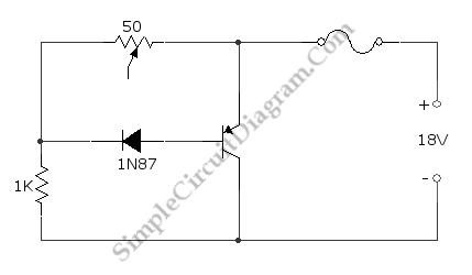
This is a transistor crowbar circuit for overvoltage protection. This circuit is used to protect any devices, when the overvoltage occurs. This circuit consist of diode, transistor, and resistor, and a fuse. The device that needs to be protected should be connected in parallel with the transistor. The 1N87 diode cut off the transistor across supply line until overvoltage occur. When the supply voltage rises above a certain level, the current will pass the diode and and flow through transistor’s base-emitter, so the transistor will short the blow the fuse to protect the device. Here is the schematic diagram of the circuit:

Discrete Overvoltage Protector for Automotive Application
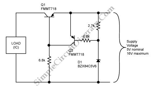
This is a circuit of discrete overvoltage protector for automotive application. There are two basic thing that must be done by protection circuit. They are prevent voltages greater than the maximum allowable from being applied to the IC pins and the protection circuit not to intrude on the normal function of the circuit. Beside that, it must be fast enough to act on any transient events. Here is the schematic diagram of discrete overvoltage protector circuit :

The PNP transistor Q1 is the main pass element of this circuit. The characteristics of this transistor will determine any power-supply voltage drops. A Zetex FMMT718 is used to minimizes the voltage drop induced by the presence of the protection circuit. As the control element for Q1, this circuit use transistor Q2, when the voltage at the power-supply input is equal to the sum of the zener voltage Q2 will turn on and turning off Q1. A typical trip voltage that is produce byD1 and Q2 is 5.85V. To keep Q1 turned on under normal circumstances, the 6.8k resistor connected to the base of Q1 by producing the current.
During overvoltage conditions, the load is disconnected by this circuit. When the overvoltage conditions is detected, the Q1 will turn off and remove power from the load, it will turn on when the conditons back to normal. The response speed of this circuit is one of the attractions of this circuit because it does not use feedback, so there are no slew-rate limitations to overcome or high-order damping effects. There are no special requirements of Q2 and almost any PNP device could be replaced but Q2 should have the same type as Q1. [Source: maxim-ic.com]
other link :
實用低功耗設計原理、器件與應用
http://www.libone.com/ebook/T/A2025956.pdf
沒有留言:
張貼留言
注意:只有此網誌的成員可以留言。