用AVR實現 PID 控制器 及其應用 (Aapplications of AVR base PID controller)
Update:2013/12/20
參考 : Matlab 2013a 外部程式語言介面 中 Video: "A new approach to embedded design for Automotive"
1. Application:
- Magnetic Levitator (磁浮控制)
- Motor Control (馬達控制)
- Temperature Control (溫控)......
- An AVR based PID magnetic levitator (磁浮控制)
- 此部分引用: blog 的文章
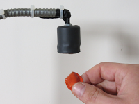
This is a magnetic levitator implemented using Atmega8 microcontroller.
Magnetic levitation is a method by which an object is suspended with no support other than magnetic fields.
To make a magnet levitate, an hall sensor is attached to a coil. The coil acts as an electromagnet, and the hall sensor measure the distance of the magnet from the coil.Magnetic levitation is a method by which an object is suspended with no support other than magnetic fields.
The coil it is driven by PWM impulses, the closer the magnet is from the hall sensor, the bigger is the duty cycle and vice versa.
The coil works only if the magnet is in a certain range, out of this range no current flow through the coil, and the system is in is idle state.
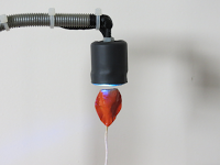
The system has to mantain the equilibrium position of the magnet, the pull force of the coil has to be equal to the gravity force that pull the magnet to ground.
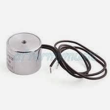
To stay on the budget, a small 12V 50N coil (ZYE1-P25/20,職流電磁鐵吸盤) is used, with this coil the system can not lift heavy loads.

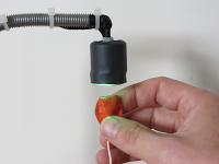
The hall sensor used it the Allegro A1302.(霍爾感測器)
Because the heavy loads limitation, i've to put the hall sensor next to the coil, this solution produce a problem, the magnet can be pull even by the ferrite core of the coil, If it gets too close to the coil. To prevent this situation we have to emitting less current to the coil.
A bigger coil and a more sensible hall sensor can lift heavier load, and also the magnet can levitate far away from the coil.
An RGB led, next to the hall sensor, is powered on when the magnet is detected.
A proportional-integral-derivative controller (PID controller) is a generic control loop feedback mechanism (controller) that calculates an "error" value as the difference between a measured process variable and a desired setpoint. The controller attempts to minimize the error by adjusting the process control inputs.
The micro runs at 8Mhz, every 1ms the hall sensor it is checked, and the PWM for the coil is adjusted. The PWM period is 1953Hz.

The PID controller parameters(PID 參數調整), and other configuration options are stored in eeprom(PID 參數儲存位置) and can be edited by a software application connected through the UART connection. The software used for this functionality is avruartconfig(PID 參數設定工具).
All the configuration values could be changed through the UART connection((PID 參數設定透過UART PORT執行) for different coil / hall sensor / magnet hardware.

應用: 作者的朋友把它應用於藝術表演 InverART 2013如下圖

Code avr_maglev01.zip
Notes
- read risk disclaimer
- excuse my bad english
2. 有關PID 概念及PID 參數調整
- 用Simulink 了解PID運作
- 用Simulink 做參數調整, Feed to AVR's EEPROM
Topic:在Simulink tuning PID 控制參數
This example shows how to automatically tune a PID Controller block using PID Tuner.
Introduction of the PID Tuner
PID Tuner provides a fast and widely applicable single-loop PID tuning method for the Simulink PID Controller blocks. With this method, you can tune PID controller parameters to achieve a robust design with the desired response time.
A typical design workflow with the PID Tuner involves the following tasks:
- Launch the PID Tuner. When launching, the software automatically computes a linear plant model from the Simulink model and designs an initial controller.
- Tune the controller in the PID Tuner by manually adjusting design criteria in two design modes. The tuner computes PID parameters that robustly stabilize the system.
- Export the parameters of the designed controller back to the PID Controller block and verify controller performance in Simulink.
Open the engine speed control model with PID Controller block and take a few moments to explore it.
打開 Mathematic 2013a 在提示符號下輸入 "<< open_system('scdspeedctrlpidblock'); "
打開 Mathematic 2013a 在提示符號下輸入 "<< open_system('scdspeedctrlpidblock'); "
open_system('scdspeedctrlpidblock');
take a few moments 出現如下:

In this example, you design a PI controller in an engine speed control loop. The goal of the design is to track the reference signal from a Simulink step block scdspeedctrlpidblock/Speed Reference. The design requirement are:
- Settling time under 5 seconds
- Zero steady-state error to the step reference input.
In this example, you stabilize the feedback loop and achieve good reference tracking performance by designing the PI controllerscdspeedctrl/PID Controller in the PID Tuner.
To launch the PID Tuner, double-click the PID Controller block to open its block dialog. In the Main tab, click Tune.

When the PID Tuner launches, the software computes a linearized plant model seen by the controller. The software automatically identifies the plant input and output, and uses the current operating point for the linearization. The plant can have any order and can have time delays.
The PID Tuner computes an initial PI controller to achieve a reasonable tradeoff between performance and robustness. By default, step reference tracking performance displays in the plot.
The following figure shows the PID Tuner dialog with the initial design:

Click the Show parameters arrow to view controller parameters P and I, and a set of performance and robustness measurements. In this example, the initial PI controller design gives a settling time of 2 seconds, which meets the requirement.
The following figure shows the parameter and performance tables:

The overshoot of the reference tracking response is about 7.5 percent. Since we still have some room before reaching the settling time limit, you could reduce the overshoot by increasing the response time. Move the response time slider to the left to increase the closed loop response time. Notice that when you adjust response time, the response plot and the controller parameters and performance measurements update.
The following figure shows an adjusted PID design with an overshoot of zero and a settling time of 4 seconds. The designed controller effectively becomes an integral-only controller.

In order to achieve zero overshoot while reducing the settling time below 2 seconds, you need to take advantage of both sliders. You need to make control response faster to reduce the settling time and increase the robustness to reduce the overshoot. For example, you can reduce the response time from 3.4 to 1.5 seconds and increase robustness from 0.6 to 0.72.
The following figure shows the closed-loop response with these settings:

After you are happy with the controller performance on the linear plant model, you can test the design on the nonlinear model. To do this, click Apply in the PID Tuner. This action writes the parameters back to the PID Controller block in the Simulink model.
The following figure shows the updated PID Controller block dialog:

The following figure shows the response of the closed-loop system:

The response shows that the new controller meets all the design requirements.
You can also use the SISO Compensator Design Tool to design the PID Controller block. When the PID Controller block belongs to a multi-loop design task. See the example "Single Loop Feedback/Prefilter Compensator Design".
bdclose('scdspeedctrlpidblock')
沒有留言:
張貼留言
注意:只有此網誌的成員可以留言。